1. Set up and test for optical fiber communication system
Optical fiber communication uses light waves as a carrier and fiber as a transmission medium to achieve information transmission, which is awidely applicable communication technology. This communication system canprovide a full-functional teaching platform for presentation &demonstration, which consists of a variety of optical active and passive devices. These devices include laser, arbitrary waveform generator (AWG),amplifier, Mach-Zehnder modulator (MZM), standard single-mode fiber (SSMF),dispersion compensation fiber (DCF), optical detector (such as avalanche photo diode), optical power meter, optical attenuator, spectrograph,programmable pattern generator (PPG), programmable error detector (PED), Optical Time Domain Reflectometry (OTDR), mixed signal oscilloscope and so on.
A variety of experiments can be done using this communication system: a) test the optical power in the whole optical link; b) test the fiber loss; c) measure the chromatic dispersion of fiber; d) measure the sensitivity of receiver; e) measure the bit error rate(BER) performance; f) observe the spectrum of the signal for analyzing the signal quality.
2. Set up and test for visible light communication system
Visible light communication is a new optical wireless communication (OWC) using the visible light as the information carrier, which has many distinct properties such as the abundance of unlicensed bandwidth, nointerference with the radio frequency (RF) band, dual use of lighting and communication and high security. Therein, the dual use function for achieving illumination and communication simultaneously will witness a big boom due to the high speed response of semiconductor light emitting diode (LED).This system includes three parts: transmitter, free space channel and receiver.The instrument used in this VLC system includes: signal generator, LED driver,direct current (DC) power, LED optical source, focusing lens, optical detector,oscilloscope, illuminometer, spectrograph and so on.
Avariety of experiments can be done using this communication system: a) test the bandwidth of LED; b) test the luminescent intensity of LED; c) measure the sensitivity of receiver; e) measure the bit error rate (BER) performance; f)observe the spectrum of the signal for analyzing the signal quality.
3. Simulation based on Matlab for optical fiber communication system
According to the optical fiber communication system set up in experiment 1, we will the Matlab software to simulate the system. In the simulation system, verify the experiment result in experiment 1 using the reasonable simulation modules. a) The transmitter module: generating binary pseudo randomcode à constellation mapping (à signal coding using in multi-carrier modulation system); b) The fiber link: the loss of G.562D SSMF is approximately 0.19 dB/km. Additionally,we model the channel as Additive White Gaussian Noise (AWGN) channel; c) The receiver module: after the photodiode transferring the optical signals into electrical signals and a low-pass filter (LPF) with certain bandwidth, the opposite operation with the transmitter is used to recover the transmitted information.
4. Introduction to the optical network simulation software based on NS-3
NS-3 is a simulation software of discrete event for network system, which mainly used for research and teaching. NS-3 is a freeware with the open source code certified by GNU GPLv2 and can be researched, improved andused by the public, which will replace the widely applicable NS-2 network software. NS-3 is built using C++ and Python with scripting capability and can be suitable for multiple operating environments such as Linux, Unix variants, OS X and Cygwin or MinGW operating in Windows platform.
The basic model of NS-3 includes five layers: Applications layer, Transport layer, Network layer, Link layer and Physical layer. The first three layers are corresponding to Applications layer, Transport layer and Internet layer in the TCP/IP model, respectively. And the last layers are corresponding to the network interface layers in in theTCP/IP model.
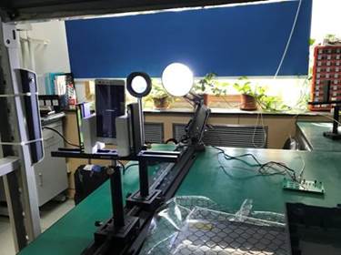
Figure1 Visible light communication system
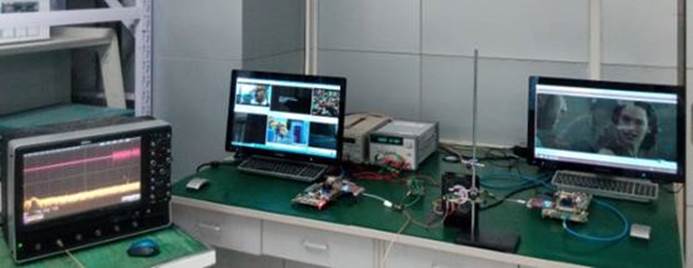
Figure2 Video transmission based on visible lightcommunication
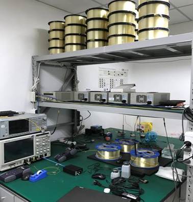
Figure 3 Fiber communication system
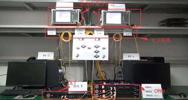
Figure410Gbit/s PON demonstration platform